Monday, December 24, 2012

Stain and Varnish

It's Christmas eve and it has been a pretty cold and snowy day here at the homestead. Above is a picture from outside and below is what I have been doing on the inside in the last couple of days.
 
I've got plastic on the floor of the garage and I have been staining and applying varnish to the cabinetry and the bench. After Christmas I'll sand and apply a second coat.
In the previous post I had the wiring all connected but I did not have it routed yet. Here's a picture after I routed all the wires. I cut grooves in the insulation with a utility knife and grooved the spars with a hand grinder. Then I carefully routed the wires into the grooves and taped them all down with aluminum tape. The wires traverse the spars in narrow bands which I have measured off and recorded so that when I screw on the plywood cover I can first mark the locations of  wires so that I don't damage them.

Well, I guess I should get out there with the snow blower before it gets dark. I'll try to do another post after new years to show anything I get done on my week off.


Saturday, December 8, 2012

Insulation Complete


Today I completed the installation of the styrofoam insulation between the spars. I used 1 1/2 inch think styrofoam that comes with plastic laminated to both sides. I glued it with contact cement. The foam sheet is very rigid and will not conform to the curved contour of the cabin unless it is kerfed. I cut kerfs every inch and a half with my table saw. The kerfs are about 3/4 of the thickness of the sheet. You apply the contact cement to the surface of the insulation and to the wood surface and allow it to dry to a state where it feels is about like the gummed surface of a 3M sticky note. At that point pressing the glued surfaces together bonds them. Contact cement dissolves polystyrene foam so you apply it only to the plastic covering of the foam sheets and try to keep it out of the kerfs and off the edges of the foam.
Here's what the kerfed sheet looks like after I have bonded it to the surface.
Ta da... Insulation has been applied in all the spaces between the spars. Next step is to get all of those electrical wires into channels and then I can put the outer skin on the trailer.


Sunday, November 25, 2012

Wiring is Finished


Above are a couple of pictures from the inside of the cabin looking at the electrical panel with covers removed.  There are eight 12V fused circuits. In hindsight perhaps I over killed it a bit on the design of the circuits. I probably could have done the job with only four by clumping multiple devices together on a single circuit. Now that it's done, however, I am very happy with how it turned out and if there is ever a problem with a fuse blowing it will be very easy to isolate because every circuit only has one or two devices on it. I'm also glad I provided plenty of room in the front for placing the fuse box. By spreading things out I was able to keep it looking fairly neat and simple to see what's going on when troubleshooting a blown fuse. In the left picture above, on the far left wall you can see a switch plate that has been connected to the wires but not yet fastened to the wall. Here is a view of it after it has been fastened to the wall:
The wall is only 1 inch thick and I found that the switches are deeper than that. In order to get them to fit I had to make a deeper pocket by adding the thickness of the switch plate. It is made of 3/8 inch plywood. I have a pair of switches like this near both  doors. One switch turns on the porch light just above the door so if you want to get out at night you can switch the porch light on from inside before you open the door. The other switch turns on the dome lights inside the cabin. If you are getting in at night you can reach in and turn on the dome lights before you enter. These switches are located less than a foot from the door so with the door open you can easily reach in to hit the switch. They are also near the head of the bed so that you can easily turn on the dome light from under the covers while you are laying down from either side of the bed.
I wanted to show you what the wiring looks like on the outside. On the driver's side outside wall of the trailer is a waterproof shore power connection which I bought at camperworld. Near  it you can see a yellow romex wire that goes over the top to feed two 110V outlets, one in the galley and the other in the cabin. From the battery you can see a red and a black pair of 8 gauge wires. They travel from the battery underneath the trailer where they enter from below through holes drilled in the framing. All of the smaller gauge black and red wires have now been tested and when I fasten in the insulating foam I will put them all into channels and give them some order. I realize that right now it kinda looks like spagetti. The amazing thing is everything worked when I powered it all up. All the outlets were live, the lights all switched like they were intended, and even the battery tender was wired right and started charging the battery as soon as I plugged in the shore power and turned on the 110V switch.

Saturday, November 10, 2012

Progress on the Bench and Electrical


This is the framework I made at the front of the teardrop to house the electrical system. The left compartment will be for 12V system and the right compartment for the 110V system. The shore power will come in through the front of the far right wall. In this picture the hole has not yet been cut. The top blue box is for the 110V fuse and main switch and the box just below it will have a power outlet which will be used to plug in the battery minder/charger.

This is a view of the same area however I have installed the cover and removed the access panels which are held in place with 4 magnets each. I want to point out some components.
1) This little metal box contains a 15 amp 110V fuse.
2) The master 110V switch is in the same unit as the fuse. I found this switch and fuse unit at Lowes.
3) This is a 110V convenience outlet into which the battery minder/charger is plugged. This outlet is wired in parallel with the other 110V outlets in the trailer.
4) This is the battery Minder/Charger. It will charge the battery when the trailer is plugged into shore power. This unit also desulphonates the battery automatically. Cool! It has indicator lights when your battery is low or if a cell is dead.
5) Oops looks like I skipped 5.
6) This is the main switch for the 12V system. This switch is rated for 40 amps it is wired directly to the positive post of the deep cycle battery using #8 wire. It was a bear soldering #8 stranded wire to the terminals on this little switch.
7) This is a 40 amp thermal breaker that automatically resets.
8) This is the 12V fuse box and grounding bus. I will show it in a later post after I have connected the circuits and added the automotive fuses. The grounding bus is connected to the negative battery post with #8 wire.
Here you can see the panel cover with the access panels in place. The panel forms the back rest for the bench. (someday it will have cushions.) I asked Cheri to take a shot of me sitting on the bench. I have plenty of headroom, I was just scrunching down to peer through the door.


In the photo above the bench is stowed. You have a good view of the piano hinge, the three metal mounts into which the legs are fastened when the bench is in use, and if you look close you can see the bolts on the top left and right which hold the bench in the stowed position. They bolt into the wall on either side.

Thursday, October 18, 2012

The Bench Design


In my requirements at the beginning of this build log I said that I wanted to be able to sit up in the trailer. Meeting that requirement involved making the trailer a little taller than most and building a bench. As you can see above I have designed a bench that folds down from the front wall of the cabin. You attach three legs to the bench when you set it down and you move two sections of the mattress up onto the bench to turn it into a padded sofa. This will come in handy on those rainy days when we need a dry place to hold up for a few hours with a good book, a deck of cards, or maybe watch a movie. When the sun comes out again you go back out and resume fishing.

I included the picture to the left, without the cushions, to give a better view of the bench which will be made of 3/4 inch ply with a hardwood lip to keep the cushion in place. Behind the bench there are four cubbys. The lower two cubbys will be for whatever you like... maybe a spare flashlight and a first aid kit. The upper cubbys will have doors on them (not shown) and will house the electrical components such as fuse box, breakers, battery charger and so on.

Thursday, September 27, 2012

Thumbnail Ideas for Paint Job


I used some of my recent time on airplanes to make these sketches on my iPad using the Brushes app. The Z and double Z at the top are rip offs from looking at old trailers. I think these are nice retro looking motifs. I have seen the blue-on-blue swoosh in the second row on more than one teardrop, often made from two or more different shades of wood. I don't know if I will use any of these but right now I am favoring the Yellow and Red Wave and the abstract Multi-Color Mural designs. If I don't use them at least they occupied a few hours of time on otherwise boring plane rides.


Saturday, September 15, 2012

Interior Cabinets are Complete


I pasted the cut away view of the cabinets from sketchup because it is a little easier to see what is going on than the photos below. In order to get the photos I need to sit down on the floor at the far end and hold the camera above my heard right against the wall so I can't see the viewfinder. That explains the kittywampus angle of some of the pics. There are two cabinets with doors on the right and left sides and two openings in the middle. The lower opening has a removable shelf that is sloped for holding a laptop. And when I say laptop I mean "entertainment center". Its what plays movies and music these days so I thought I might as well get with the times and build a place for it here. The small shelf above is for the "sound system". That's where we will set the jambox when we are playing movies or listening to music. If you don't know what a jambox is you should check the link. It puts out great sound and operates wireless from on bluetooth. I can sync it to my laptop or my ipad, its battery powered so I can use it in the trailer or carry it out to the picnic table. I toyed around for a long time with the idea of installing a car stereo system and a flat screen TV but the laptop idea just seemed to make the most sense. It can play DVDs and it can store nearly my entire CD collection of music.

The upper left pic is with the cabinet doors open and the computer shelf stowed. The center pic is with the cabinet doors closed and the upper right pic shows the computer shelf in position and my laptop sitting on it. You can see two openings below the computer shelf. One will have a 110V outlet and other 12V. I have also wired 12V to the back of the upper compartment where the jambox will be. There is another 12V wire pair hanging down from the cabinets. That will be wired to a small electric dashboard heater. An electric heater will draw too much current to use very long but I think it will take the chill out of the air when we get out of bed on cold mornings.

Sunday, September 2, 2012

Starting Work Inside the Cabin


The pictures above are from the process of gluing together three sheets of 1/8 inch masonite which would become the inner curved front wall and ceiling of the cabin or "headliner". I saw this method described by Mike Schneider in his Generic Benroy plans. I cut the sheets to the inner width of the cabin minus 1/8 inch to give a little room for error. I also cut a 3-inch strip of masonite for each joint. The joints were then glued using gorilla glue by butting the ends together and using the 3-inch strip to overlap each side of the joint by 1.5 inches. I put a strip of glad wrap on the top and bottom to keep the glue from sticking to the garage floor and the boxes. Boxes of canned food were used as weights to do the clamping. I let the glue set overnight. I learned a valuable lesson which will benefit you. Next time I will use waxed paper instead of plastic wrap because, while the plastic wrap protected against glue adhering to other surfaces, the gorilla glue adhered quite well to the plastic wrap so I had a pretty big job of sanding to remove the plastic wrap from the surface. In the upper right picture you see the glue joints after they have been sanded and then covered with bondo. After the bondo set I went over the joints with my orbital sander to produce a smooth and continuous headliner sheet that is 1/8 inch less than the cabin width and a couple of inches longer than needed. This long thin sheet proved impossible for one person to manipulate so, with help of my daughter Sydney, I inserted the sheet for a test fit. I marked the exact length, the removed it and cut it to the correct length. The  final installation was done by applying construction adhesive to the inside of all of the spars then inserting the headliner again and screwing it in place. 


In the pictures above you can see the installed headliner from two views. Outside and inside.

I also got started on the cabinet inside the cabin. More to come on this in my next post. Tomorrow is labor day so I hope to have this looking a lot more like a cabinet by the end of the day.

Tuesday, July 17, 2012

Electrical Diagram

I worked out this wiring diagram for the Woodsman. There will be an on board battery charger/tender so that when I am plugged into shore power the battery will be charged and maintained. In the past I have some experience with deep cycle batteries from trying to maintain batteries for an electric trolling motor. You don't want to let them set over the winter without being connected to a tender. The tender (or minder) will monitor the voltage on the battery and add charge as needed which preserves the life of the battery and allows you to get maximum charge cycles and performance for the full life of the battery. Other than that the wiring will be pretty basic. There will be a master switch and old school 20A fuse to protect the 120V system as well as a GFCI breaker on one of the outlets for safety. Then a 40A breaker and master switch on the 12V circuit with a fuse box that has positions for 8 automotive fuses and a grounding bus. The battery will be in a box on the tongue of the trailer and the other components will be housed in a cabinet near the front of the trailer. I will show these in subsequent posts. 

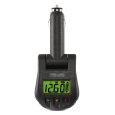
I checked into the meters I would need to install to have a constant read out of voltage and current. Although it would be nice to have these, I decided not to permanently install digital meters. I am using LEDs and florescent lighting to keep the current draw as low as possible. Mainly I would like an easy way to check the voltage to make sure I don't drain the battery too far which would affect its lifetime. I can do this with one of the devices shown below, they cost around $15. You just plug it into one of your 12V outlets to check the voltage at any time.


Sunday, July 8, 2012

Galley Cabinet Completed

Here is the completed upper cabinet of the galley (doors off). The shelves are made of 3/8 inch ply. They have a lip to keep items from falling off the shelves during transport. The lip is of 3/4 inch by 3/4 inch pine. I made a special cubby to hold my lantern.


I would like to point out a couple of things in the photo above that relate to wiring. Notice the left wall of the interior of the cabinet is a "false" wall that encloses the wires that come in from the ceiling and are routed into an electrical chase below the floor of the cabinet where they feed the 120V and 12V outlets of the galley. Notice also the small rectangle at the bottom center of the cabinet. This is an enclosure that covers wiring that is routed up out of the chase and through the back wall. This wiring will serve the cabin.

This is the cabinet just before I added the shelves. I took this picture so that you can see how the wires are routed before I covered them up.

The cabinetwork of the galley is finally complete.It took a lot more Saturdays than I thought it would take but I am very happy with the result. I'm excited about the next step of the build. In the next step I will be installing the inner lining of the ceiling in the cabin.

Sunday, July 1, 2012

Sliding Doors of Galley


I completed the sliding doors for the galley. Why sliding doors? Hinged cabinet doors won't work very well here because if you set something on the counter top then open a hinged door it will sweep it right off the counter. With sliding doors you can have something on the counter and still open the cabinet. The casing for the doors is made of ash and the sliding doors are of 3/8 inch ply. The bottom piece has two openings for the convenience outlets. One of the outlets will be wired with a 12V socket and the other will have a 120V GFI double outlet. 

The assembled casing for the sliding doors is shown on the upper left. On the upper right is the end view of the top and bottom sliding door slots set next to each other. As you can see the slots on the upper portion are deeper than the slots on the lower portion. 3/8 inch deep on the bottom and 5/8 inch deep on top. This is done so that you can insert and remove the doors by pushing them up into the top slot until the bottom clears the lower slot. After the finish is on I will rub a candle in the slots to deposit a little wax to make the doors slide smoothly.
The casing is fastened into the trailer using 3 1/2 inch screws that go through the wall from the outside into the side of the casing.


Sunday, June 17, 2012

Drawers are finished


OK, I have a new found respect for cabinet makers. It took a long time and a lot of patience to make these drawers. In the picture on the top left you see the completed bottom part of the galley with all of the drawer faces on. There are two roll-out shelves in the left portion of the galley. The bottom shelf will hold the cooler and the top shelf will hold the camp stove. Both have heavy duty drawer sliders with ball bearings that are rated for 100 lbs. There are also four drawers and a cubby that fits the water jug. In the top right picture I have all of the drawers extended. This was taken before I put all of the faces on the drawers. To make the drawer faces I used the same sheet of 3/4 inch ply that I used to make the counter top. All around the edges of the ply wood I cut and glued 1/2 inch strips of poplar. They came out very nice and should look great when they are stained and varnished. 


In the picture above you can see the backside of the cabinet front that I made from poplar for the drawers. This was all assembled using pocket screws and gorilla glue. You can see some small metal L brackets that I used to fasten the cabinet frame in place. I applied construction glue also as an added measure when I attached it. After the cabinet frame was in place I built the drawer boxes of 1/2 inch ply with 3/8 inch ply on the bottoms of the drawers. The drawer boxes came out super strong. I had to put wooden spacers in place of various thicknesses before installing the drawer hardware so that everything fit perfectly. It took a lot of measuring cutting and glueing to get everything to go together but I think it turned out pretty nice. Now I can start working on the upper part of the galley.

Saturday, May 26, 2012

The Roof and Front is Framed


As you can see I finished the framing on the curve that composes the front and roof of the trailer. For this I ripped 2X4s on my table saw to make boards that are 1 1/2" by 1 1/2" then I cut them all to the same length. They are spaced about 16 inches apart. I fastened them in place by applying gorilla glue to the ends and screwing a 3 1/2 inch wood screw from the outside of the trailer into the center of the board. before placing the screw I drilled a pilot hole and countersunk the screw hole so the top of the screw is slightly recessed. This way I can fill the screw head recesses with bondo when I finish the exterior. After these boards were screwed in place I can feel a significant difference in the strength of the whole unit. It now feels really solid when you grab hold and try to shake it.

I also started work on the galley. I will make a slide out tray for the cooler and just above it will be another one for the camp stove.  The compartment on the right side will eventually have three drawers and there will be a fourth drawer in the space above the water container. I have never made drawers before so that will be an adventure. The counter top is made from 3/4 inch plywood. I glued a 1 1/2 by 3/4 inch strip of oak to the front of the counter top to give it better hardness against denting. I will finish the counter top by applying a thick coating of transparent epoxy. This will produce a hard surface to protect the wood against scratches and dents.


I made a change to the shape of the trailer on the fly as I was building. Now I have applied the change to the drawing shown above. I made the trailer somewhat taller than I originally drew it. To maximize the use of my lumber I decided to make the trailer 1 1/2 sheets high (six feet) . I have corrected the drawing so now the photographs of the project look more like the CAD drawings. I'm 6'4" and I want to be able to sit up in the trailer so I figure I can use the extra height.

I should point out also that I spent a couple of hours today sanding the curves of the walls before I did the framing. When cutting curves with a hand jigsaw it is easy to deviate from the line by 1/16" or more. I bought some 60 grit paper for my orbital sander and worked the edges all the way around until I had sanded out all of the non-uniformities and made the curves smooth.

I have pasted below the drawing of the wall frames without the skin so that you can see the framing details for the walls. In this view you can also see the 14 inch square frame in the top for the ventilation fan.